Showing posts with label Networking. Show all posts

Monday, May 16, 2016

User Bandwidth Management Hotspot in Bypass (IP Binding)


User Bandwidth Management Hotspot in Bypass (IP Binding)

Technological developments require that all people have a smart phone digenggamannya, even the day the price of smart phones more affordable by all audiences in Indonesia. Automatically needs of the Internet is increasingly important for many people. No wonder if any crowded places such as offices, hotels, campuses, malls and so provide hotspot service. So many have concluded Wireless Hotspot must be through the media, if you are one of them please read the article below
If you already studied the article at the link we have agreed that in Mikrotik Hotspot is a system to provide authentication features to the user that will use the network. But we can also give privileges to some users that do not need authentication implementation examples there are more details in the article below
After Users in bypass, meaning the user is not able to do the bandwidth limitation using the User Profile. To overcome this we can do a number of ways depending IP bindings we do.
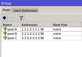
IP Binding by allocating a specific IP
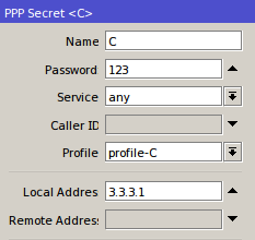
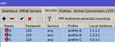
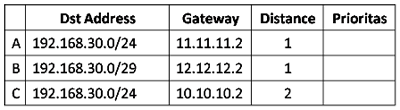
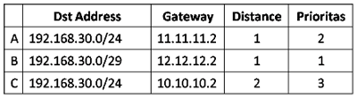
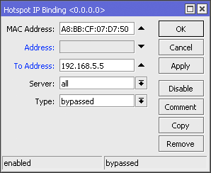
In this method, we will allocate special ip address which will be given to the user bypasses. The ip router will allocate the bypass user based on mac-address, so the ip address user who bypassed unchanged - a fox. Just as making static-lease on a DHCP server settings. Do I go to the menu IP >> >> Hotspot IP Bindings.   Then add the Mac Address of the user who will be bypassed and decide to address it.
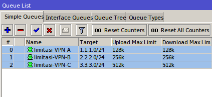
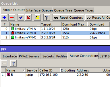
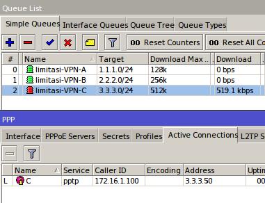
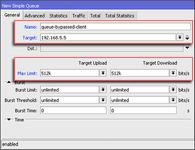
If using this bypass means, to perform management bandiwdth we just add Simple Queue leading to the IP we have set in to the IP Address Bindings.

IP Binding without allocation of IP Address
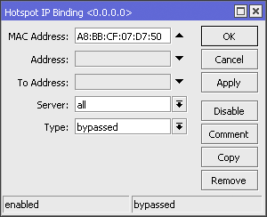
With this method, the user simply bypassed by mac-address user device. Ip address that will didapatakn random user depending on the DHCP server. How to bypass, select the menu Hotspot IP >> >> IP Bindings. Then add the Mac Address of the user who will be bypassed.
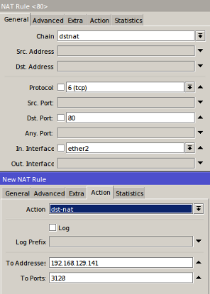
If using bypass this way, to be able to perform user management are 
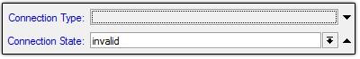
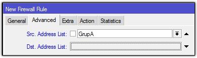
bypassed we should mark the first packets through the router with mac 
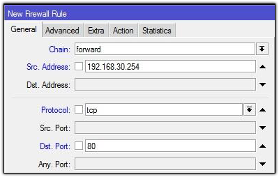
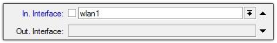
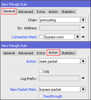
address. We can use the features of Mangle. First we make a mark-conection first: Firewall IP >> >> >> Add Mangle
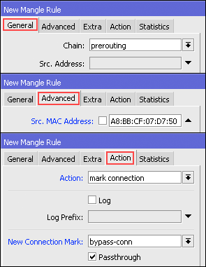
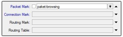
The next step makes Mark Packet based mac-connection that was made before, via menu Firewall IP >> >> >> Add Mangle
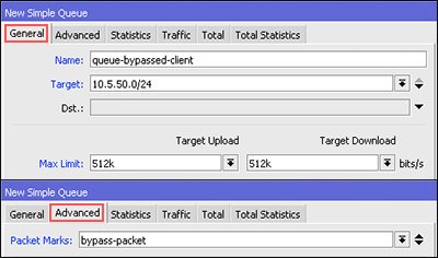
Lastly, we can make a new bandwidth management using the Simple Queue based mark-packet that has been made in the mangle. Do not forget, the parameter "Target" please fill in your hotspot network segment.

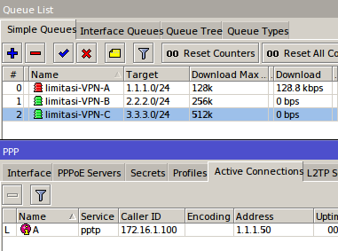
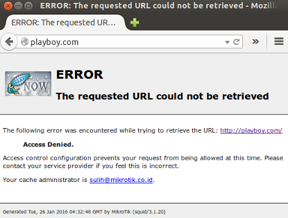
If the above steps are finished, then try to do bandwidth test user side are bypassed. Actually there are many ways you can do for the user management in bypass, like PCQ, static-leases, etc. Both the above steps are just as simple alternatives that can be used for bandwidth menagement user who bypassed the hotspot network.

User Database Migration Manager


User Database Migration Manager

When we wanted to create a hotspot service, it would be easier if we use a system to handle AAA (Authentication, Authorization and Accounting), fortunately in mikrotik already provided a tool that is usermanager. Usermanager contained in the database used to store information service includes the hotspot users, PPP users, DHCP Leases, Wireless AccessList, and RouterOS users.
Opening the business hotspot with daily user is not too difficult when we lose data, eg loss of user data that we have made. But a big problem if we already have a lot of users. Therefore perform a backup of data for maintenance purposes is an activity that can not be abandoned.
This time we will discuss how to do usermanager database backup and restore the database to a new router if the router is damaged.
Configuration
For example the present case there are two routers which first router has been installed user-manager and also have the data. Kemudain second router that the newly installed user-manager and there is no data. And for the second router the data will be drawn from the first router.
First, the router 1 we will "backup / save" database of user-manager. To process we will use the New Terminal. New Terminal we would type the command / tool user-manager database save name = [filename].
Automatically created a file with extension * .umb. For example we will name the 'dbase-R1.umb'. Well, this is the file we are going to "export" database to a second router.
Second, we will export this file to the user database-manager on Router 2. Previously, we will enter the first file into the localhost (menu Files) on Router 2. We can use FTP (for Linux, Mac OS) or "drag- drop '(for Windows).
After work we put into the file menu Router 2, then we are going to export into databse Router 2 using the New Terminal. For exports we use the command / tool user-manager database load name = [filename].
When it appears a confirmation, press "Y" and the process of export / restore will run. When successful there will be a notice "User-Manager Database Restored".
Final Check
To determine whether the data has been entered into the Router 2 we can check directly to the user-manager features. Keep in mind, when we are already logged in user-manager Router 2 to be able to see the results we need to first log out and log back in to update the current session.
Display Data Router 1
Display Data Router 2

Bandwidth Management VPN Users


Bandwidth Management VPN Users

Management bandwidth usage is an important thing. With this we can avoid the monopoly of the use of bandwidth. So that we can set the bandwidth usage evenly or can we use to give priorities to the specific user.

Then, what if the user is a VPN connection users of our network. There are several ways that can be applied, that is Dynamic and Static. For dynamic methods we have discussed in previous articles here .
With this dynamic method when there is a VPN user login will be given allotments of bandwidth as we specify. This may be quite easy if the VPN user is not too much and tend to be static.

If the VPN user the many and are mobile will be very hard for us to divide how much bandwidth is fitted to each of the user. Moreover, if the VPN user is divided into multiple accounts and each account has a different network.

As an example the case with the VPN user account A walk in the network 1.1.1.0/24, with the network 2.2.2.0/24 account B, and C account with the network 3.3.3.0/24. And each account will have different bandwidth allocation. To account A -> 128kbps, account B -> 256kbps, account C -> 512kbps. The bandwidth allocation will be divided evenly on each network. When there is addition or subtraction automatically User VPN router bandwidth will be split evenly and can also maximize the use of existing bandwidth.


VPN configuration

The first configuration we will make 'IP Pool' for allocation of IP addresses for each account from the VPN. Go to the menu I P -> Pool -> click the Add [+].


After we make our next IP Pool activate the VPN service. This time the VPN service to be used is PPTP. To enable entry to the PPP menu -> Interface -> click the command button 'PPTP Serve r'. Then uncheck 'Enabled'.


Then we create a new profile for the VPN account A, B, and C. In the same menu select Tab 'Profiles'. The profile settings will be used to define the parameter 'Remote Address' in secret. So that the allocation of IP addresses to the user can be automatically according to the network that we set.


Well, eventually we memeliki 3 new profile for each VPN account.
The next step we create a user account for VPN. Pembuatannya on Tab 'Secret'.


So that there will be 3 to konkesi PPTP VPN account, namely A, B, and C.


Queue Configuration for Bandwidth Management

After we configure the VPN server, then we will make use of simple queue bandwidth management.


Tested

We will do the testing if the configuration we can run well. For this test using the bandwidth test from the PC / Laptop connected to a VPN network that we created earlier.

When a user VPN using account A and in trying to do a bandwidth test, then if the configuration goes well, limitation queue will use VPN-A-limitation bandwidth allocation in accordance with the previous provisions.


A limitation Test Account

It also will be the same when the VPN user is connected primarily to account B and C. Each will get a bandwidth limitation in accordance with which we set earlier.


Limitations Test Account B


Test Account Limitations C

Friday, May 13, 2016

MikroTik combination with External Proxy


MikroTik combination with External Proxy


Proxy not a stranger in the world of Mikrotik.
 Mikrotik itself has proxy feature that can be quite simple. Many users Mikrotik then add external proxy in order to use features that are more complex than internal features of proxy. The question is, whether they have a significant performance difference? In this article we will try to do test the performance of internal and external proxy. 

Configuring External Proxy with MikroTik

To test this, we will use an external application proxy that is commonly used, namely Squid. Step-by-step installation and configuration of the application of this squid can we get references on the internet. And do not worry a lot of references that have been using the Indonesian language for this application many users even in Indonesia.
After installation and configuration of Squid is complete, then we will do the setting transparent proxy. This works for all traffic accessing the HTTP (TCP Protocol, Port 80) is deflected into the Proxy server. Configuration of the transparent proxy this we will do in the MikroTik Router using NAT Firewall feature. The steps are as follows: 


Go to the menu IP -> Firewall -> Nat -> click the Add [+]. Then specify the parametersChain, Protocol, Dst.Port, in accordance with the above view. In a special parameter.Interface stay we adjust the link that leads to a local network. Furthermore, the Tab Action, Action parameters for use dst-nat and we also specify the parameters To Addresses and Ports To address the Proxy server and the port used. In this example the proxy server using the IP address and the port is 192 168 129 141 3128.

Now, with the above step has been formed transparent proxy. Next we will do test whether the configuration that we have done goes well or not. We will try to access the website we have added to the list 'Blocking' on the Proxy server. 


If the error text is displayed as described above, the configuration we have been successful.

Internal configuration MikroTik Proxy (Web Proxy)

After we tried to use the External Proxy, now we'll try to feature contained in the Proxy MikroTik. As we have seen MikroTik adding a feature that can be used to perform the access management of user / client. Such features are Web Proxy. How the steps to configure this feature can be seen in the discussion of the previous article here . 

On these links already explained how we enable and also setting the web proxy feature is that access a web page can be set here. And on the link it has also been described how to create a transparent proxy to redirect traffic to Web Proxy feature. For transparent proxy is also the same as we have done before, but the difference here is the selection of parameters Action. If we use the Internal Proxy (Web Proxy), the action we have set with the option 'Redirect' because the system proxy server located at localhost (router).Meanwhile, if we use the External Proxy (Squid), the action we have chosen is 'dst-nat'.

Well, if Inetrnal proxy configuration (Web Proxy) we have done, now we will try to access the web that we have entered kedaftar 'Deny' in the Web Proxy. As before, if the configuration we are going well or not.


And if it displays an error on the web browser as above, then the web proxy configuration has been successful.

Performance Test (Pros & Cons)

Once we tried to configure and implement the above two types of proxy servers, we can make the performance of each proxy server. To perform the analysis of the performance of the proxy, there beberpa tool that we can use. Among such Grinder, Gatling, Tsung,Apache JMeter. The tools we can get it for free and also the configuration steps in the application developer's website.

This time we will try the application Tsung to analyze the performance of proxy that we have built before.


With these tools we can see the performance of the proxy server to view a table or graph.There beberpa parameters to be analyzed seeprti Response Times, Network Throughput, Transactions Statistics, Counter Statistics. 

Well, from here we can draw a conclusion as to the performance of each proxy server.Where, for the use of simple, both the proxy server is not too much different, but to side configuration External Proxy (Squid) more custom. 

:: Internal Proxy (Web Proxy) ::

  • Easy installation process.
  • Easy to configure (there are GUI display).
  • If the size of storage on a small router, then it's not recommended to enable proxy caching feature, or at least not only used to cache small files.

:: External Proxy (Squid) ::

  • Easy to install, simply add NAT Mikrotik side.
  • A little tricky to configuration (must use scripting).
  • Suitable for more advanced needs.
  • The storage capacity is relatively large, because the use of a PC so that the proxy cache feature can run optimally

Sunday, July 6, 2014

Smokeping to Monitor Network Latency in UBUNTU

Smokeping to Monitor Network Latency in UBUNTU

ping
Recently I was troubleshooting a network where concerned Admin complained that they frequently lost connectivity with the Internet. Sometimes pings replies works okay but latency gets high or timeout / breaks occurs. So I decided to setup mrtg base ping graph to monitor ping latency. The custom made mrtg ping probe worked fine and can provide an overview on target ping / rtt and Downtime in a nice manner,
BUT . . . . . . . . . . . . . . . . . . .
I was thinking far ahead , I was thinking for much more advanced latency and pin point graphs which can show ping latency / rtt / loss in much more detailed way. I recalled my memory from old days when I used to monitor my old network with variety of tools and scripts and suddenly a name popped in my mind " SMOKEPING " , yes this was the tool I was looking for.
SmokePing generates graphs that can reveal the quality (packet loss and latency variability) & reach-ability of your IP address from several distributed locations. SmokePing is a network latency monitor. It measures network latency to a configurable set of destinations on the network, and displays its findings in easy-to-read Web pages. It uses RRDtool as its logging and graphing back-end, making the system very efficient. The presentation of the data on the Web is done through a CGI with some AJAX capabilities for interactive graph exploration.

  • In this article I will show you howto install smokeping on UBUNTU 10/12

First install required components along with smokeping and apache2 (you can remove Apache or any other component if its not required or already installed)
aptitude install smokeping curl libauthen-radius-perl libnet-ldap-perl libnet-dns-perl libio-socket-ssl-perl libnet-telnet-perl libsocket6-perl libio-socket-inet6-perl apache2
Once all is installed, we have to modify few configuration files.
Open following following ...
nano /etc/smokeping/config.d/pathnames
now remove sendmail entry by adding # sign to to comment the sendmail line, usually the first line.
Save and exit.
Now open following file
nano /etc/smokeping/config.d/Targets
Now REMOVE all previous lines , and copy paste following
*** Targets ***  probe = FPing    menu = Top  title = Network Latency Grapher  remark = Welcome to the SmokePing website of <b>ZAIB (Pvt) Ltd.</b> <br> Here you will learn all about the latency of our network.<br><br><br><br><br> This page is maintained by ZAIB. (Pvt) ltd . <br><br>Support Email: aacable@hotmail.com<br>Web: http://aacable.wordpress.com    ### YOU CAN CHANGE THE FOLLOWING ACCORDING TO YOUR NETWORK ###    + Ping    menu = WAN Connectivity  title = WAS Side Network    ++ yahoo    menu = yahoo  title = yahoo ping report  host = yahoo.com    ++ google    menu = google  title = Google ping report  host = google.com    ### YOU CAN CHANGE FOLLOWING ACCORDING TO YOUR NETWORK ###  + Ping2    menu = LAN Connectivity  title = LAN Side Network    ++ Mikrotik    menu = Mikrotik  title = Mikrotik PPP ping report  host = 10.10.0.1    ++ Billing    menu = Billing  title = Radius billing Server ping report  host = 10.0.0.2
save and exit.
now restart smokeping service by
service smokeping restart
and access it via browser.
Results should be something like below image...
lan
wan-report
More info on previous smokeping article based on FEDORA 10 , (Old version) Just for idea

Wednesday, June 25, 2014

Wireless Point-to-Point Mikrotik

Wireless Point-to-Point Mikrotik - Wireless Point-to-Point is a wireless communication connection between two points, where the host is connected only with one client. Wireless Point-to-Point (P2P) using two Mikrotik Mikrotik + Directional Antenna (Grid, Yagi, Sectoral, etc.). Application of Wireless Point-to-point on Mikrotik RouterOS license requires a minimum of level 3 in bridge mode - station.

The device used is Mikrotik Mikrotik Outdoor which has resistance to a wide range of weather conditions, for example using the RB 433. Mikrotik will later be installed in the tower of his communication with directional antenna. For installation Mikrotik and its own antenna must consider the condition of the surrounding environment.

Line of Sight

Line of Sight (LoS) is a straight path between the sender (transmitter) and receiver (receiver) that is free of obstructions. So the air path between the AP and the client as much as possible that nothing is blocking, such as buildings, trees, hills, etc.. If there is a barrier then the Wi-Fi connectivity will not be maximized, will not even be able to connect.

Fresnel Zone

Fresnel Zone is the area around a straight line between the antenna (LoS) is used as a medium frequency propagation. In addition to the barrier-free LoS, Fresnel Zone area is also as much as possible its not too much of a barrier.

For more details, please see the following picture:

Antenna Alignment

Antenna Alignment is the direction of the antenna used. Antenna client should lead to the AP antennas, and vice versa. The angle and direction of the antenna must also be considered, because if it does not lead to better then the signal will not be received with the maximum.

Mikrotik 1 as an Access Point (AP)

In Mikrotik 1 is used as an AP with Bridge mode. Why is Bridge? Because of the Point-to-Point only two-way communication occurs only between the AP and the client. If the Client is more than one means that including Point-to-Multipoint. Well, Bridge mode allows only one client alone who can connect to the AP.

Mikrotik 2 as a Client

Client connected to the AP via Wireless use Station mode. At Station usual mode does not support L2 bridging, so it can not be used to make the network transparent wireless bridge. If you use a regular Station mode then must use routing, instead of her bridge.

Monday, June 23, 2014

Selection of Path Routing

Selection of Path Routing

Routing is a mechanism of delivery of data packets transmitted from one network to another network. In a router, usually has a routing table that stores information or routing path to be used when there is data transmission through the router. In certain cases to get to a destination, the router has only one gateway, such as a router must have a network that connects many different segments. A simple example can be seen in the following topology:
Then how the router determines its route selection?. Which Gateway Router 1 will be used to get to the server? When there is more than one routing rule, the router has a routing path calculation mechanisms that will be used routers for data transmission. Routing path selection is based on several parameters: dst-address and the distance of each routing rule.

  • First, the router will choose the rule dst-address routing to the most specific.
  • Then the router will see the value in the Distance parameter in each routing rule, the smaller the Distance, then the rule will be used.
  • If there are multiple routing rule with the same dst-address-specific and the same distance, then the router will choose the Random (round robin).
From the previous topology, routing rule obtained as images.
How does the order of priority lanes that will be used Router 1?. We will try to discuss route selection mechanism based router. Keep in mind, traffic is traffic that will be transmitted from Router 1 to the server with the IP address to 192.168.30.3. Take a look at the routing rule above, for the purpose of IP 192.168.30.3 dst-address = 192.168.30.0/29 more specific than dst-address = 192.168.30.0/24, so the rule B will be used as a first priority. Then the rule which will be a priority 2 and 3?. Consider the rule A and C. Both have the same dst-address - the same / 24, but the value of the distance of the two different rule. Between A and C routing rule, the router will choose A, because the distance to the rule parameter value A is smaller than C. It could be concluded that the rule of the discussion was going to come answer as follows:
By default distance value is determined according to the type of routing is applied, for example to Static Route = 1, OSPF = 110, RIP = 120, and so on. However, the value of the distance parameter can also be changed, to make a simple failover mechanism. An example implementation of a simple failover is when there are two routing rules with different distance, note the following routing rule:
In these examples, the main route is to go to 192.168.30.0/24 gateway 11.11.11.2. If the gateway 11.11.11.2 end / die, it will automatically update the routing rule that will use the router for data transmission will shift to using the backup path, which is the gateway 10.10.10.2. Network admin not to bother - bother to change the routing table information manually.

INSTALL THE CABLE UTP STRAIGHT TYPE AND CROSS

INSTALL THE CABLE UTP STRAIGHT AND CROSS


before you practice, there is some hardware that you need to prepare, including :


  • UTP (Unshielded Twisted Pair). UTP cables are frequently used categori 5 UTP cable (UTP Cat-5). why? for Cat-5 UTP cable support data transfer up to 100 Mbps. This cable consists of 8 small that have different colors. The cable color is orange, orange and white, blue, white, green, green, white, brown, white chocolate.

  • the second is the RJ-45 jack. jack is similar to a home telephone jack. only the larger size. RJ-45 jack consists of 8 pins, according to the number of UTP cables

  • crimping tool or crimping pliers. hardware that is similar to a pair of pliers. however, unlike its function pliers in general. crimping tool is useful to clip the cable to the RJ-45 jack. 
all the above hardware can be found at most computer stores. the price is not too expensive.

 UTP cable straight type
 

I will now discuss how to install. The first is how to install UTP cable straight type. for it to do the following steps:


  • peeled end of the wire about 1 cm, so that the small wires that are inside look.


  • attach the cables and straightens. then collated and the trim on the white color is orange, orange, green, white, blue, white blue, green, white and chocolate brown. after it cut the edges so that the average of each other.


  • after a structured cabling, RJ-45 jack grab. as I said earlier this jack consists of 8 pins. pin 1 of the jack is located adalahpin the left if your facing the pin position. sequential to the right is the jack 2, 3, 4, and so on. 


  • then insert the wires into the RJ-45 jack in the order was as follows:


  1. Orange-white on pin 1
  2. Orange to pin 2
  3. Green-white on pin 3
  4. Blue on pin 4
  5. Blue and white on pin 5
  6. Green on pin 6
  7. White chocolate on pin 7
  8. Brown on pin 8 
         insert the cable until the tip is stuck in the jack.

  
  • insert the RJ-45 jack which is mounted with the cable before crimping pliers in your mouth corresponding to the pin RJ-45 jack in the mouth pliers. now had a jack flops tangcrimping pin sticking up all over the wiring. usually if the pin is stuck jack will give voice "click".
now you've finished installing the RJ-45 jack on the end of the first cable. to the second end of the cable, the steps are the same as the first one end of the cable installation. to repeat the earlier steps to install the RJ-45 jack on the end of the second cable.
UTP cable straight type arrangement you can see in the picture below:


Caption:
H    : green
HP : green and white
OP : orange and white
B    : blue
BP : blue and white
O    : orange
CP : white chocolate
C    : brown


UTP cable type cross
 
how to install UTP cable straight type I described earlier. Now I will discuss about how to install the type of cross UTP cable. UTP cabling to cross almost the same type by placing a straight UTP cable types. about the same as before the technical installation. the difference is the color sequence of wires at the second end of the cable. The first end of the cable, the cable structure with UTP cable straight type arrangement are:


  • Orange to pin 1
  • Orange-white on pin 2
  • Green on pin 3
  • Blue on pin 4
  • Blue and white on pin 5
  • Green-white on pin 6
  • White chocolate on pin 7
  • Brown on pin 8
to the second end of the cable, the color arrangement different from the first end. As for the arrangement of the colors is:

  • Green-white on pin 1
  • Green on pin 2
  • Orange-white on pin 3
  • Blue on pin 4
  • Blue and white on pin 5
  • Orange to pin 6
  • White chocolate on pin 7
  • Brown on pin 8
composition had wiring you can see in the picture below


 Caption:
H    : green
HP : green and white
OP : orange and white
B    : blue
BP : blue and white
O    : orange
CP : white chocolate
C    : brown


the end result will cross UTP cable types like this:


 Caption:
H    : green
HP : green and white
OP : orange and white
B    : blue
BP : blue and white
O    : orange
CP : white chocolate
C    : brown


the conclusion is if you plug in the UTP straight type arrangement of colors on both ends of the cable is the same. whereas UTP installation way cross type, color composition different from the first end of the cable end of the second cable.

tutorial how to install this type of straight UTP cable and cross type.

Implementation of Firewall Filters

Implementation of Firewall Filters


In general, firewall filtering is usually done by defining the IP address, both the src-address and dst-address. Suppose you want to block client computer that has a certain ip or when doing block certain web based ip to the web. Firewalls are not only used to block the client that can not access a particular resource, but it is also used to protect the local network from external threats, such as viruses or hacker attacks. Usually the attack from the internet is done from a lot of IP so that it will be difficult for us to do only with the protection of IP based. Well, actually there are many ways in addition to filtering based on IP Addres, for example based on protocol and port. Here's an example of implementation by utilizing some of the parameters in the filter firewall features.

Protocol and Port
The use of ports and protocols is usually combined with an IP address. Suppose you want the client can not browse, but can still FTP, then you can create a firewall rule that performs block TCP port 80. When you click the drop down in the protocol, it will display any protocol option that will we filter. This parameter will we need when we want to block the application where the application uses a specific protocol and port.


Interface
Interface outline there are 2, the input interface and output interface. How to determine this is to look at the interface where the trafick entered into the router, and which interface traffick from the exit to leave the router. Suppose you connect to the internet through a router proxy, then you ping www.mikrotik.co.id from your laptop, then the input interface is the interface connected to your laptop, and the output interface is the interface connected to the Internet. An example application is when you want to maintain the security of the router, you do not want the router can be accessed from the internet. Of these cases you can do filter the incoming connection to the router with a direct in-interface option on the interface connected to the Internet.


P2P parameter
There is actually a fairly easy way and simple to perform such filtering against traffick P2P torrent or eDonkey. If you previously used a lot of rules, you can simplify the P2P parameters specify filters in the firewall rule. If you click on the drop down, it would appear that p2p program information can be filtered by the firewall.


Mangle
We usually make a mangle to mark packets / connections, then we use for bandwidth management. But we also can make a mangle to perform filtering. Firewall filters can not perform tagging in packets or connections, but we can combine firewall mangle and filter. First, we mark the first packet or connection with mangle, then we define in the firewall filters.


Connection State
If you do not want any packet - invalid packet passing on your network, you can also perform filtering by defining the parameters of the connection state. Invalid package is a package that has no connection and is not useful so it will only burden the network resources. We can do drop the package - this package by defining the parameters of the connection state.


Address List
There are times when we want to do filtering against some ip that is not sequential or random. If we make a rule one by one, it will become tiresome. With these conditions, we can apply the IP grouping makes "address list". First, make a list of ip in the address list, and then apply the filter in your rule. Options for adding the "Address List" in the firewall on the Advanced tab. There are two types of address list, "Src. Address List" and "Dst. Address List. Src Address List is a list of resources that connect to ip, ip Dst Address List is a goal to be accessible.


Layer 7 Protocol
If you are familiar with regexp, you can also apply filtering on layer7 using firewall filters. In the proxy, adding regexp can be done in the menu Layer 7 Protocol. Once you add regexp, you can perform filtering with Layer 7 Protocol defines the filter rule you created. Please note that the use RegExp, will require higher CPU recource than usual rule.


Content
When we want to do block the website, one of the steps are quite easy to do this is to perform a filter based on content. Content is the string that is displayed on the web page. That way, the website that has a string kida fill in the content will be filtered by the firewall. Suppose we want to block www.facebook.com then simply browse content with a string parameter "facebook" and drop action, the website either HTTP or HTTPS facebook inaccessible.


Mac address
When we do a filter by IP address, a user sometimes naughty by replacing ip address. To overcome this mischief, we can apply filtering by mac-address. We record the mac address used information that user, then we add the parameters Src. Mac Address in firewall rule us. With so long as the user is still using the same device, he continued to be changed ip filter though.


Time
One alternative solution other than we have to bother making a scheduler and scripts, we can utilize the time in firewall feature filters. This feature will determine when a firewall rule is executed. Not only to determine hours, this feature can also be used to determine any day of the rule runs. Suppose we want to block facebook in office hours, then we can create a firewall rule to block facebook run from 08:00 to 16:00 hours apart on Saturday and Sunday. Before you create a firewall rule with the parameter "time", make sure you've set NTP on your router so that the router time according to real time.


When you create a firewall rule, try to create a specific rule. The more specific rule that we make, the more optimal the rule also will run.

http://freaks.co.id