Showing posts with label Networking. Show all posts

Monday, June 23, 2014

Features Logging In Mikrotik

Features Logging In Mikrotik

One feature that is visible on his Mikrotik simple and probably also forgotten but have a fairly important function is LOGGING feature.
RouterOS is able to perform a variety of recording information system events and status of the router.

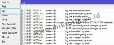
By default RouterOS will keep records of all activities and processes that occur in the router and keeps a record (log) of the RAM. List of record (log) can be seen on the menu / log.
Logs are located in menu / logs will be lost once we restart the router because the log is stored only in RAM.

Examples of the appearance of the menus / log via Winbox.

In network troubleshooting will be more effective by analyzing the logs of the Router prior to knowing what the process is already happening. So it will be easier to map the problem and determine a solution.

Too much information that we get if we just look at the menu / log, so it may be difficult for analysis. For that we can make the topic of what will be recorded and will be stored or displayed where the log.

Besides stored in memory (RAM) routers, logs can also be stored as a file on the storage router, sent via email or syslog server is displayed on the device itself.

This setting can be done in the menu / system logging.

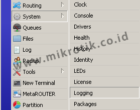
If you notice there are two tabs in the menu / system logging, the Rules Tab and Tab Action.

Tab Action (/ system logging action)
Used for setting the log storage methods.
There are 5 Type of Action that we can use:
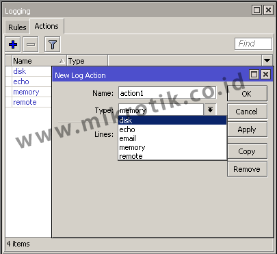

1. The Disk Type
With this type of logs will be stored as text files and are saved in the system storage router itself. We can always set the current log file name is stored in the File Name parameter. Can also set how many lines of the log file that is stored in each of his, could set the parameters of Lines per file.

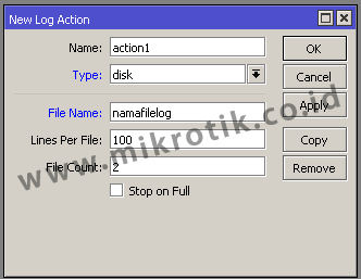
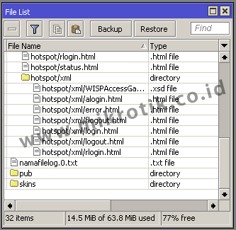
The log file can then be downloaded from the Files menu router and can be opened with a text editor on your PC
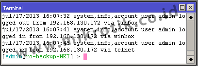
2. Type Echo
By using this type of router log will be displayed at the New Terminal (Winbox) or when we use the remote CLI (direct console)

3. Type email
Logs will be sent to the email that we have set. In order to function then we have to do before setting smtp server that will be used in the menu / tool e-mail

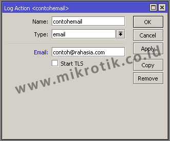
How often will the same as the email delivery Router how often the update log. Our advice, do not use public email services (like Yahoo or Gmail) because when sending emails too often public email services usually will consider it as spam.
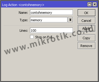
4. The Memory Type
Logs will be stored in RAM Routers and can take a look at the log menu. Because only the logs are stored in RAM will be lost / can not read anymore after rebooting the router.
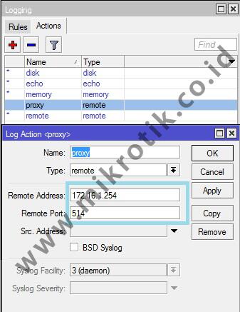
5. Type Remote
Logs will be sent to any device that runs the syslog server. We live designate the machine running the syslog server by entering the IP address.

If action has been created the next step we have to create a log rules.

Rules tab (/ system logging rules)
On the tab this rule we can make the topic or what services will we noted in the log. So that we can observe a process or service is more specific.

There are many services in our router and the new rules is that we make, we can specify one or more topic that we will record in the log.

The following example we will record all webproxy process is simple (! Debug).

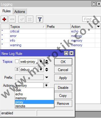
Topic! Debug is optional. This means that no topic! Debug logging webproxy will also keep running. ! Debug log is used to keep the display is not too detailed. By default if we specify a logging topic, there is a process of detailed information that occurs on a machine that sometimes even confusing.

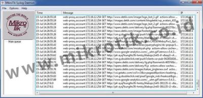
Example when logging topic WebProxy (! Debug) with remote action so that the log will be sent to the machine (PC) that runs the syslog server (172.16.1.254) with a simple syslog application of Mikrotik for Windows named MTSyslog.

The following figure shows the log display is seen at the application MTSyslog
MTSyslog application can be downloaded free of charge here .


By using this logging function we do not need to observe the processes that occur on the router continuously at all times. We simply view the results of the record (log) of existing processes to see what is going on as long as you do not observe the router directly.

http://freakscontent.blogspot.com/

TCP / IP Introduction to OSI Layer

 TCP / IP Introduction to OSI Layer

By the time we start the step into the science of computer network, the first thing we learn is usually TCP / IP. TCP / IP can be in such language analogy. When humans exchange information, people will speak in a language that can be understood by speakers and listeners. So is the case with the host computer or in a network. Communication and exchange of information in order to be well established, it takes the same language. Although different brands of the network host - different, the host can still communicate with other hosts because it uses the same communication standard, namely TCP / IP. Internet Protocol was first designed in the 1980s. But in the 1990's where the internet is increasingly popular and more and more hosts, ranging bemunculan protocol that can only be used by certain circles, or protocol made by certain manufacturers that are not necessarily compatible with other protocols from other plants as well. So in the end the body the International Standards Organization (ISO) to standardize protocols that are currently known to the protocol of the Open Systems Interconnection or OSI abbreviated. The OSI reference model is widened and the basic concepts of a theory of how the protocol. In the development of TCP / IP is used as a de facto standard.

OSI Layer
When the ISO (International Standard Organization) to standardize the protocol, it creates a standard reference model containing the workings of the protocol. Reference model which was then called the Open Systems Interconnection (OSI). Based on the document recommendation X.200, the OSI standard has 7 layers. Each layer has a different function definitions.

Layer 7: Application Layer
Is the layer where the interaction with the end user interface applications that work using the network functionality, make arrangements of how the application works using the network resources, to then memberika message when an error occurs. Some of the services and protocols that are in this layer as HTTP, FTP, SMTP, etc..

Layer 6: Presentation Layer
This layer works to translate the data format to be transmitted by the application over the network, into a format that can be transmitted by the network. In this layer the data will be encrypted or in-description.

Layer 5: Session Layer
Session layer defines how connections can be made, maintained, or destroyed. In this layer there are protocols Name Recognition, NFS and SMB.

Layer 4: Transport Layer
This layer will split data into packets of data and provide the serial number on the data packets that can be rearranged when it came to the side of the goal. In addition, at this level, will determine the protocol that will be used to transmit the data, eg TCP protocol. This protocol will transmit data packets, as well as to ensure that the packet received successfully (acknowledgment), and retransmit the packets that are lost or damaged on the way.

Layer 3: Network Layer
Network layer will make header for packets that contain IP information, both the sender's IP data and IP destination data. Under certain conditions, this layer will also perform routing through the use of internetworking routers and layer 3 switches.

Layer 2: The data-link layer
Befungsi to determine how the data bits are grouped into a format called a frame. In addition, at this level of error correction, flow control, addressing hardware (such as the Media Access Control address (MAC address)), and determine how the network devices such as hubs, bridges, repeaters, and a layer 2 switch operates. IEEE 802 specification, dividing it into two levels level children, the layer Logical Link Control (LLC) layer and the Media Access Control (MAC).

Layer 1: Physical Layer
Layer Physcal work by defining the network transmission media, signaling method, bit synchronization, network architectures (such as Ethernet or Token Ring), network topology and cabling. In addition, this level also defines how the Network Interface Card (NIC) can interact with cable or radio media.

The process of sending data can pass through each layer analogy like when we send a letter. The letter is the data that will be sent (layer 7 -> 5). Then, according to standard delivery, we put the letter into an envelope (layer - 4). So that we can sent the letter, we need to add the address where the mail is sent, as well as who the sender of the letter was (Layer - 3). Furthermore, the letter we submitted to the expedition, and the expedition we will be sending a letter earlier (layer - 2 & 1).

Packet Header
In the previous review we discuss how a process of data transmitted, now we will try to unload data. What's in sebiah data so that data can be transmitted. analogy when we send data on the Internet is like sending a POS, it can be said that the data is the contents of the letter, then the packet headers is an envelope, stamp, address, and other equipment. Packet header provides some additional information. If we surgical ditrasnmisikan a data packet using ipv4, then the contents of the data packets can be seen as shown below:


IPVer: Storing information used IP version (IPv4 or IPv6).
IHL (IP Header Leght): Information overall length of the data packet header. The minimum length of the IP header is 20 bits, and the maximum length is 24 bits.
TOS: It is a field in the IPv4 header has a length of 8 bits and is used to indicate the type of Quality of Service (QoS) that is used by the datagram in question to be submitted to the internetwork routers. Implementation of this TOS is usually when we do the limitations of HIT in the web proxy service proxy or VOIP.
Bit 16 Total Length: 16 bits The contents of this gives the overall size information packet (fragment) including header and data. Information is displayed in a format bytes
16 Bit Identification, Fragment Offset Flag / Length: At the time of ip packet goes on the internet, this pack will probably pass some routers can not handle the size of the packet, for example, the value of Maximum transmission unit (MTU) that is smaller than its IP datagram size, then The package will be broken or fragmented packets - smaller package would then be reassembled later. These parameters will be used for fragmentation and rearrangement.
TTL: There is the possibility of an IP packet wander aimlessly in the Internet network. Case example of an error routing or routing loops. In order for this package is not circling the Internet forever, the TTL value will be deducted each time a data packet passes through a router. When the TTL value of a packet of data has been exhausted or has a value of 0, then the packet is dropped or discarded.
Protocol: Contains information what protocol is used to transmit data.
16 Bit Header checksum: information is calculated based on the calculation of the value of the IP header content. Used to determine if there is an error at the time of transmission of the data.
32 Bit Source IP Address: 32 bits data packet source IP information.
Bit 32 Destination IP Address: 32 bits IP destination information of data packets.
Options (if any): This parameter includes rarely used, has a variable length, from 0 to a multiple of 32 bits. This parameter can be used to store a value for the security option, Record Route, Time Stamp, etc..
Data: Contains the data that is transmitted.

From the packet header information above, at the end of a data can be sent from one host to another.

http://freakscontent.blogspot.com/ 

Wiring

Wiring

At the time we speak, we say that the voice could reach the ear associates that we are speaking, it takes a trasnmisi media, in this case air. Each computer also requires a network transmission medium. Transmission medium there are many computer networks, can use the media cable, radio waves / wireless, infrared, bluetooth, or the current popular media uses light (fiber optic). Most of the transmission medium used today are the type of cable. Each type of cable typically have different capabilities and specifications, therefore, made the introduction of cable types.
Twisted Pair Cables
Twisted-pair cable is a type of cable used for telephone communications and most modern Ethernet networks. A pair of wires forming a path to transmit data. The pair made kebel entwined to provide protection against "crosstalk" or interference generated by the pair of adjacent wires. When an electric current flows through a wire, will create small circular magnetic field around the wire. When two wires in an electrical circuit are placed close together, and their magnetic fields are opposite of each other, thus the two magnetic fields will cancel out each other. The cable pair will also eliminate any magnetic field from the outside wires. By turning the cable will be able to enhance the effects of magnetic fields cancel each other out and effectively be able to provide protection to the cable network. There are two general types on the type of twisted-pair cable, unshielded twisted pair (UTP) and shielded twisted pair (STP)
UTP
UTP cable is a transmission medium that consists of 4 pairs of wires. UTP cables are used in a variety of tissues. Each of the eight individual copper wires in UTP cable is covered by an insulating material. In addition, in each pair of wires that are wrapped around each other.
UTP cables are often combined with the use of Registered Jack 45 (RJ-45) connector. RJ-45 connector eight cable is typically used to connect a computer to a local-area network (LAN), especially Ethernet.
UTP cable has four pairs of copper wire with a size 22 or 24 gauge (gauge is the standard cable pengurkuran). One factor that distinguishes other UTP cable with one cable UTP cable has an impedance of 100 ohms. although formerly UTP cable is said to have a slow transfer speed, but in its development are now able to pass traffic up to 1 Gbps. Maximum UTP cable length is 100 meters.
STP
Almost the same with just any pair UTP wire wrapped with metal foil. These four pairs of comrades will be wrapped again with metal foil or metal fibers. The goal is around to reduce noise disturbances such as electric, magnetic fields, etc.. STP can be combined with STP Data Connector or it could be with RJ45. STP maximum cable length is 100 meters. Because it is more resistant than noise, STP cable is more widely used for outdoor applications, such as cable leading to the AP on the tower.
Standard Wiring
Each wire in the cable networks have different functions so that we can not crimping origin. There are two wiring standards most commonly used are: EIA / TIA 568A and EIA / TIA 568B, by way of cable sususan sort by color.
EIA / TIA 568A
The composition of the cable with a standard EIA / TIA 568A begins with green white cable. the cable arrangement would be as follows:
1. The White Green
2. Green
3. White Orange
4. Blue
5. White Blue
6. Orange
7. White Chocolate
8. Brown

EIA / TIA 568B
The composition of the cable with a standard EIA / TIA 568B begins with orange and white colors. Complete sequence of the cable with the standard as follows:
1. The White Orange
2. Orange
3. White Green
4. Blue
5. White Blue
6. Green
7. White Chocolate
8. Brown
Cross Cable & Straight
By the time we talk about sorting pin cable network, of Crossover and Straight designations often we hear.   Straight cable is a cable that ends with the beginning of the end of the end of the cable has the same pin order. Examples of straight cable with standard sequencing pin EIA / TIA 568B
And then end with the back end of the same - the same pin arrangement EIA / TIA 568B. Then for a cross cable, as its name means opposite pin arrangement, or the opposite.
Straight and cross cable is the same - just connect the device to other devices in a computer network, but a device that can be associated with each - each of these different types of cables. Derikut table devices to be connected and cables needed:
Auto MDI / MDI-X
The latest devices today typically supports Auto MDI / MDI-X. Devices that already support Auto MDI / MDI-X can be connected by a straight cable and cross cable. The device will detect whether the connection requires a crossover, and it will automatically use the MDI or MDIX configuration to match the opponent's connection.
Wiring
Before doing the wiring, there are several considerations that must be done first, such as how many computers will be connected. Then the distance between the nodes.
Equipment Needed
to do the wiring, prepare some of the following tools:
  • Cable UTP / STP, specify how long the cable, and the amount of wiring required. Cable quality is also different in each brand.
  • RJ45, which will be used as a cable connector.
  • Crimping Tool, for installing konekstor RJ45 cable to UTP / STP, usually disebit crimping.
  • LAN Tester, when the network cable manufacturing process has been completed, the last thing you need to do is testing. LAN tester is used to perform tsting on the cable network. Indication of whether the cable berfungdi normally be of indicators buyi LAN tester beeps or it could be from the LED lights.
Wiring Method
  1. Peel the end of the UTP cable, approximately 2 cm.
  2. Open the cable strands, straighten and urutankan compliant cables TIA / EIA 368B
  3. Once the order is according to the standard, cut and flatten the ends of the cable, input cable is straight and aligned into the RJ-45 connector, and make sure all cables are correct position.
  4. Perform using crimping tools crimping, press crimping tool and make sure all the pins (brass) on the RJ-45 connectors already "bite" of each cable. Once finished at the other end, do it again at the other end.
  5. The final step is check the cable pulled you created earlier by using the LAN tester, how to enter each end of the cable (RJ-45) masing2 to an available port on the LAN tester, make sure all the lights turn on and the LED lights up in accordance with the order of cable we make.
Make sure the end of the UTP cable that has an RJ-45 connector is attached properly, the cable sheath (blue) also took a bit get into the connector.

http://freakscontent.blogspot.com/ 

Sunday, June 22, 2014

Load Balance using PCC method

Load Balance using PCC method

Load balance on the proxy is a technique to distribute the traffic load on two or more lines in a balanced connection, so that traffic can run optimally, maximize throughput, minimize response time and avoid overload on one connection point.During this time many of us who think incorrectly, that by using the loadbalance two connection lines, the large bandwidth will we get into a doubling of bandwidth before using loadbalance (accumulation of both the bandwidth). This needs to be clear in advance, that will not add bulk to loadbalance bandwidth we get, but it only served to divide the traffic from both the bandwidth that can be used in a balanced way.With this article, we will prove that the use of mathematical formulas loadbalancing not like 512 + 256 = 768, but 512 + 256 = 512 + 256, or 512 + 256 = 256 + 256 + 256.In this article we use RB433UAH with the following conditions:1. Ether1 and ether2 connected to different ISPs with large bandwdith different. ISP1 and ISP2 at 512kbps for 256kbps.2. We will use the internal web-proxy and use OpenDNS.3. RouterOS you are using version 4.5 because the PCC has become a popular feature at the 3:24 version.If the above condition is different from your local network conditions, the configuration of which we will describe here should you adjust the configuration to your local network.Basic ConfigurationHere is a network topology and the IP address that we will use


/ip address
add address=192.168.101.2/30 interface=ether1
add address=192.168.102.2/30 interface=ether2
add address=10.10.10.1/24 interface=wlan2
/ip dns
set allow-remote-requests=yes primary-dns=208.67.222.222 secondary-dns=208.67.220.220 


For client connections, we use the wireless connection on wlan2 the client IP range 10.10.10.2 s / d 10.10.10.254 netmask 255.255.255.0, which is attached to the IP 10.10.10.1 wlan2 serves as a gateway and dns server from the client. If you are using one of the DNS from your ISP, then there will be additional mangle would we give a thickAfter configuring the IP and DNS are correct, we have to install a default route to each of us to ISP gateway IP routers forward all traffic that is not connected to it to the gateway. Here we use the check-gateway feature is useful if one of the gateways we broke up, then the connection will be deflected to the other gateway./ Ip routeadd dst-address = 0.0.0.0 / 0 gateway = 192.168.101.1 distance = 1 check-gateway = pingadd dst-address = 0.0.0.0 / 0 gateway = 192.168.102.1 distance = 2 check-gateway = pingTo setup the Access Point so that the PC can connect to the wireless client, we use the command/ Interface wirelesswlan2 set mode = ap-bridge band = 2.4ghz-b / g ssid = MikroTik disabled = noIn order for the client pc can connect to the internet, we also have to change the private IP to a public IP client that is in us is the public interface ether1 and ether2./ Ip firewall natadd action = masquerade chain = srcnat out-interface = ether1add action = masquerade chain = srcnat out-interface = ether2Until this step, the router and the PC clients are able to access the Internet. Ping the router or the good of the client pc to the internet. If not successful, check your configuration again.